|
libpruio
0.6.8
Fast and easy Digital/Analog Input/Output for Beaglebones
|


|
|
libpruio
0.6.8
Fast and easy Digital/Analog Input/Output for Beaglebones
|
|
Tool for creating a customized device tree overlay. More...
#include "pruiotools.bas"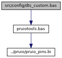
Go to the source code of this file.
Macros | |
| #define | FILE_NAME /* "pruio_custom" */ |
| The file name. | |
| #define | VERS_NAME /* "00A0" */ |
| The version. | |
Variables | |
| VAR | TARG_PATH = "/lib/firmware" |
| The folder where to place the compiled overlay binary. | |
| VAR | COMPATIBL = "ti,beaglebone-black" |
| The BB model. | |
Tool for creating a customized device tree overlay.
This file contains the FB source code for a helper tool creating a customized device tree overlay. Adapt this code for your needs, compile it and run the executable. Unlike the dts_universal.bas tool, this code declares (and claims) only the pins which get specified in the code. The tool will create a device tree overlay source file in the current directory, and, if you execute the binary with root privileges, this overlay gets compiled and installed in the specified directory (usually /lib/firmware).
The created customized overlay sets the pinmuxing in a fixed manner. Your code can run in user space (without root privileges). (But the overlay can also provide pinmuxing capability at run-time, if you specify more than one mode for a header pin. Root privileges are required to change the mode.)
In order to create a customized overlays, first add your pin configurations to the source code (explained later). Then compile the code by executing
fbc -w all dts_custom.bas
and run the executable
./dts_custom
This will create your customized overlay source file named pruio_custom-00A0.dts in the current directory.
In order to create and install that overlay, execute with root privileges and add the destination path as parameter
sudo ./dts_custom /lib/firmware
In order to add your pin configurations, first you should know that the code defines a global array (type STRING) to hold the pin modes, which is called M(). This array contains an entry for each CPU ball, 110 entries in total, all empty at startup. To claim a header pin, fill its array entry with the desired mode by a line like
M(P9_41) = CHR(7 + PU + RX)
This line will define header pin P9_41 in mode 7 (GPIO) with pull-up recistor (PU) and receiver enabled (RX). This example uses enumerators PinModes from file pruiotools.bas for better readability. Find further examples for pin configurations in files P8.bi, `P9.bi and JTag.bi.
Once you adapted the code to your needs, compile and run it by
fbc -w all dts_custom.bas
sudo ./dts_custom /lib/firmware
Then load the overlay by (kernel <= 3.8)
sudo su
echo pruio_custom > /sys/devices/bone_capemgr.?/slots
exit
or on kernel versions > 3.8
sudo su
echo pruio_custom > /sys/devices/platform/bone_capemgr/slots
exit
(Or execute this echo ... command in your boot sequence. Or use capemgr to load the overlay. See Pinmuxing for further information.)
Licence: GPLv3, Copyright 2014-2023 by Thomas{ doT ]Freiherr[ At ]gmx[ DoT }net
Definition in file dts_custom.bas.