|
libpruio
0.6.8
Fast and easy Digital/Analog Input/Output for Beaglebones
|


|
|
libpruio
0.6.8
Fast and easy Digital/Analog Input/Output for Beaglebones
|
|
Structure for GPIO subsystem features, containing all functions and variables to handle the subsystems. More...
Public Member Functions | |
| GpioUdt (BYVAL_AS_Pruio__PTR) | |
| The constructor for the GPIO features. More... | |
| FUNCTION_CDECL_AS_ZSTRING_PTR | initialize () |
| Initialize the register context after running the pasm_init.p instructions (private). More... | |
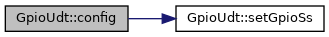
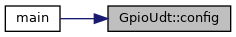
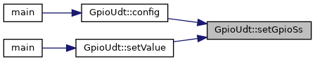
| FUNCTION_CDECL_AS_ZSTRING_PTR | config (BYVAL_AS_UInt8, BYVAL_AS_UInt8) |
| Configure a GPIO. More... | |
| SUB_CDECL | setGpioSs () |
| Set registers in GPIO subsystem. More... | |
| FUNCTION_CDECL_AS_ZSTRING_PTR | flush (BYVAL_AS_UInt8) |
| Flush all output lines at a GPIO subsystem. More... | |
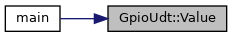
| FUNCTION_CDECL_AS_Int32 | Value (BYVAL_AS_UInt8) |
| Get the state of a GPIO. More... | |
| FUNCTION_CDECL_AS_ZSTRING_PTR | setValue (BYVAL_AS_UInt8, BYVAL_AS_UInt8) |
| Set the state of a GPIO. More... | |
Public Attributes | |
| Pruio__PTR | Top |
| Pointer to the calling PruIo instance. | |
| GpioSet_PTR | Init [PRUIO_AZ_GPIO+1] |
| Initial subsystem configuration, used in the destructor PruIo::~PruIo(). | |
| GpioSet_PTR | Conf [PRUIO_AZ_GPIO+1] |
| Current subsystem configuration, used in PruIo::config(). | |
| GpioArr_PTR | Raw [PRUIO_AZ_GPIO+1] |
| Pointer to current raw subsystem data (IO), all 32 bits. | |
| UInt32 | InitParA |
| Offset to read data block offset. | |
| UInt32 | Mask |
| The bit mask to manipulate. | |
| UInt8 | Mode |
| The mode for pinmuxing. | |
| UInt8 | Indx |
| The GPIO subsystem index. | |
| UInt8 | Fe1 |
| Future expansion. | |
| UInt8 | Fe2 |
| Future expansion. | |
| ZSTRING_PTR | E0 = "GPIO subsystem not enabled" |
| Common error message. | |
| ZSTRING_PTR | E1 = "no GPIO mode" |
| Common error message. | |
| ZSTRING_PTR | E2 = "no GPIO pin" |
| Common error message. | |
Structure for GPIO subsystem features, containing all functions and variables to handle the subsystems.
This UDT contains the member function to control the features in each of the four GPIO subsystems included in the TI AM335x CPU and the related variables.
Definition at line 81 of file pruio_gpio.bi.
| GpioUdt::GpioUdt | ( | BYVAL_AS_Pruio__PTR | T | ) |
The constructor for the GPIO features.
| T | A pointer of the calling PruIo structure. |
The constructor prepares the DRam parameters to run the pasm_init.p instructions. The adresses of the subsystems and the adresses of the clock registers get prepared, and the index of the last parameter gets stored to compute the offset in the Init and Conf data blocks.
Definition at line 28 of file pruio_gpio.bas.

| FUNCTION_CDECL_AS_ZSTRING_PTR GpioUdt::config | ( | BYVAL_AS_UInt8 | Ball, |
| BYVAL_AS_UInt8 | Mo = CAST(UInt8, PRUIO_GPIO_IN_0) |
||
| ) |
Configure a GPIO.
| Ball | The CPU ball number to test. |
| Mo | The modus to set (as Control Module pad register value). |
This function is used to configure a digital pin for GPIO. Use the macros defined in pruio.bi to specify the pin number in parameter Ball for a pin on the Beaglebone headers (ie P8_03 selects pin 3 on header P8).
Parameter Modus specifies the pinmux mode for the ARM control module (see ARM Reference Guide, chapter 9 for details). By default the pin gets configured as input pin with pulldown resistor. Other configurations are prepared as enumerators PinMuxing :
| macro name | Description |
|---|---|
| PRUIO_GPIO_IN | open input pin (no resistor) |
| PRUIO_GPIO_IN_0 | low input pin (with pulldown resistor) |
| PRUIO_GPIO_IN_1 | high input pin (with pullup resistor) |
| PRUIO_GPIO_OUT0 | output pin set to low (no resistor) |
| PRUIO_GPIO_OUT1 | output pin set to high (no resistor) |
Wrapper function (C or Python): pruio_gpio_config().
Definition at line 130 of file pruio_gpio.bas.
| FUNCTION_CDECL_AS_ZSTRING_PTR GpioUdt::flush | ( | BYVAL_AS_UInt8 | Indx | ) |
Flush all output lines at a GPIO subsystem.
| Indx | The subsystem index [0-3] |
Transfer new data to the GPIO subsystem registers
in order to set multiple output lines in a single step (no latency between the output transitions). First, modify the related member variables in the array PruIo::Gpio::Conf(Indx) and then flush those values to the hardware. Find example code in src/examples/stepper2.bas
Definition at line 208 of file pruio_gpio.bas.
| FUNCTION_CDECL_AS_ZSTRING_PTR GpioUdt::initialize | ( | ) |
Initialize the register context after running the pasm_init.p instructions (private).
This is a private function, designed to be called from the main constructor PruIo::PruIo(). It sets the pointers to the Init and Conf structures in the data blocks. And it initializes some register context, if the subsystem woke up and is enabled.
Definition at line 59 of file pruio_gpio.bas.

| SUB GpioUdt::setGpioSs | ( | ) |
Set registers in GPIO subsystem.
This procedure writes new values to the related registers of the GPIO subsystem to specify the required direction (in or out), and in case of output the required state (low or high). It's low-level and private, not intended for public usage.
Definition at line 158 of file pruio_gpio.bas.
| FUNCTION_CDECL_AS_ZSTRING_PTR GpioUdt::setValue | ( | BYVAL_AS_UInt8 | Ball, |
| BYVAL_AS_UInt8 | Mo = 0 |
||
| ) |
Set the state of a GPIO.
| Ball | The CPU ball number to test. |
| Mo | The state to set (0 = low, high otherwise). |
This function is used to set the state of an output GPIO. Set parameter Ball to the required header pin (=CPU ball) by using the convenience macros defined in(ie. P8_03 selects pin 3 on header P8). Use pruio_pins_pocket.bi or pruio_pins_blue.bi for Pocket Beaglebone or Beaglebone Blue boards.
Parameter Mo specifies either the state to set (0 or 1). Or it specifies the pinmux mode to test and the state in the MSB.
Wrapper function (C or Python): pruio_gpio_setValue().
Definition at line 242 of file pruio_gpio.bas.


| FUNCTION_CDECL_AS_Int32 GpioUdt::Value | ( | BYVAL_AS_UInt8 | Ball | ) |
Get the state of a GPIO.
| Ball | The CPU ball number to test. |
This function is used to get the state of a digital pin (GPIO). Use the macros defined in pruio.bi to specify the pin number in parameter Ball for a pin on the Beaglebone headers (ie P8_03 selects pin 3 on header P8).
It's possible to get the state of a CPU ball (not connected to a header), also. In this case you need to find the matching CPU ball number and pass it in as the parameter Ball.
The function returns the state of input and output pins. Return values are
| Value | Description |
|---|---|
| 1 | GPIO is in high state |
| 0 | GPIO is in low state |
| -1 | error (undefined ball number) |
Wrapper function (C or Python): pruio_gpio_Value().
Definition at line 293 of file pruio_gpio.bas.