|
libpruio
0.6.8
Fast and easy Digital/Analog Input/Output for Beaglebones
|


|
|
libpruio
0.6.8
Fast and easy Digital/Analog Input/Output for Beaglebones
|
|
Main structure, binding all components together. More...
Public Member Functions | |
| FUNCTION_CDECL_AS_ZSTRING_PTR() | setPin (BYVAL_AS_Pruio__PTR Top, BYVAL_AS_UInt8 Ball, BYVAL_AS_UInt8 Mo) |
| Interface for pinmuxing function (internal). More... | |
| PruIo (BYVAL_AS_UInt16, BYVAL_AS_UInt8, BYVAL_AS_UInt32, BYVAL_AS_UInt8) | |
| Constructor, initialize subsystems, create default configuration. More... | |
| ~PruIo () | |
| Destructor to restore configurations and clear memory. More... | |
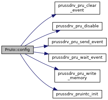
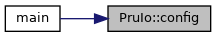
| FUNCTION_CDECL_AS_ZSTRING_PTR | config (BYVAL_AS_UInt32, BYVAL_AS_UInt32, BYVAL_AS_UInt32, BYVAL_AS_UInt16) |
| Load configuration from host (ARM) to driver (PRU). More... | |
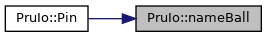
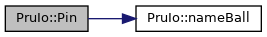
| FUNCTION_CDECL_AS_ZSTRING_PTR | Pin (BYVAL_AS_UInt8, BYVAL_AS_UInt8) |
| Create a text description for a CPU ball configuration. More... | |
| FUNCTION_CDECL_AS_ZSTRING_PTR | nameBall (BYVAL_AS_UInt8) |
| Get header pin connected to CPU ball. More... | |
| FUNCTION_CDECL_AS_ZSTRING_PTR | rb_start () |
| Start ring buffer mode. More... | |
| FUNCTION_CDECL_AS_ZSTRING_PTR | mm_start (BYVAL_AS_UInt32, BYVAL_AS_UInt32, BYVAL_AS_UInt32, BYVAL_AS_UInt32) |
| Start a measurement in MM. More... | |
Public Attributes | |
| ZSTRING_PTR | Errr = 0 |
| Pointer for error messages, see chapter Messages. | |
| AdcUdt_PTR | Adc |
| Pointer to AdcUdt class. | |
| GpioUdt_PTR | Gpio |
| Pointer to GpioUdt class. | |
| PwmssUdt_PTR | PwmSS |
| Pointer to PwmssUdt class. | |
| TimerUdt_PTR | TimSS |
| Pointer to TimerUdt class. | |
| PwmMod_PTR | Pwm |
| Pointer to PwmMod class for PWM features (in PWMSS subsystems). | |
| CapMod_PTR | Cap |
| Pointer to CapMod class for CAP features (in PWMSS subsystems). | |
| QepMod_PTR | Qep |
| Pointer to QepMod class for QEP features (in PWMSS subsystems). | |
| TimerUdt_PTR | Tim |
| Pointer to TimerUdt class for TIMER features (for homogenous API). | |
| UInt32_PTR | DRam |
| Pointer to access PRU DRam, see chapter Memory Organisation. | |
| BallSet_PTR | Init |
| The subsystems register data at start-up (to restore when finished). | |
| BallSet_PTR | Conf |
| The subsystems register data used by libpruio (current local data to be uploaded by PruIo::Config() ). | |
| ANY_PTR | ERam |
| Pointer to read PRU external ram, see chapter Memory Organisation. | |
| ANY_PTR | DInit |
| Pointer to block of subsystems initial data. | |
| ANY_PTR | DConf |
| Pointer to block of subsystems configuration data. | |
| ANY_PTR | MOffs |
| Configuration offset for modules. | |
| UInt8_PTR | BallInit |
| Pointer for original Ball configuration. | |
| UInt8_PTR | BallConf |
| Pointer to ball configuration (CPU pin muxing). | |
| UInt32 | EAddr |
| The address of the external memory (PRUSS-DDR). | |
| UInt32 | ESize |
| The size of the external memory (PRUSS-DDR). | |
| UInt32 | DSize |
| The size of a data block (DInit or DConf). | |
| UInt32 | PruNo |
| The PRU number to use (defaults to 1). | |
| UInt32 | PruIRam |
| The PRU instruction ram to load. | |
| UInt32 | PruDRam |
| The PRU data ram. | |
| UInt32 | PruIntNo |
| The PRU interrupt number. | |
| Int16 | ParOffs |
| The offset for the parameters of a module. | |
| Int16 | DevAct |
| Active subsystems. | |
| UInt32 | BbType |
| Type of Beaglebone board (2 = Blue, 1 = Pocket, 0 = others) | |
| UInt32 | MuxFnr |
| Pinmuxing file number, if any. | |
| ZSTRING_PTR | MuxAcc |
| Pinmuxing ocp path, if no LKM. | |
| UInt8 | BallGpio [PRUIO_AZ_BALL+1] |
| list of GPIO numbers, corresponding to ball index More... | |
| tpruss_intc_initdata_PTR | IntcInit = @DEF_INTC_INIT |
| interrupt settings | |
| UInt32 | WaitCycles |
| Counter: ARM waiting for PRU. | |
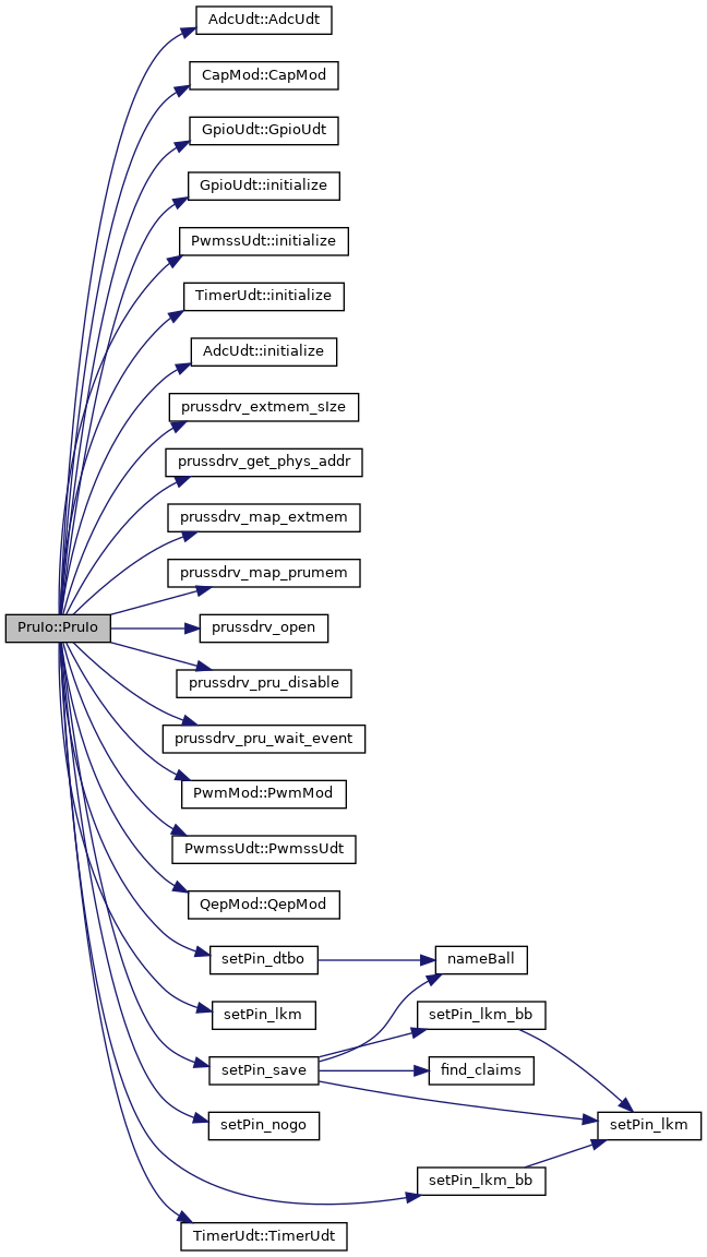
Main structure, binding all components together.
This UDT glues all together. It downloads and start software on the PRUSS, controls the initialisation and configuration processes and reads or writes the pinmux configurations.
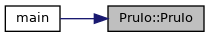
| PruIo::PruIo | ( | BYVAL_AS_UInt16 | Act = PRUIO_DEF_ACTIVE, |
| BYVAL_AS_UInt8 | Av = PRUIO_DEF_AVRAGE, |
||
| BYVAL_AS_UInt32 | OpD = PRUIO_DEF_ODELAY, |
||
| BYVAL_AS_UInt8 | SaD = PRUIO_DEF_SDELAY |
||
| ) |
Constructor, initialize subsystems, create default configuration.
| Act | Mask to specify active subsystems (defaults to all active). |
| Av | Avaraging for default steps (0 to 16, defaults to 0). |
| OpD | Open delay for default steps (0 to 0x3FFFF, defaults to 0x98) |
| SaD | Sample delay for default steps (0 to 255, defaults to 0). |
The constructor tries to
It reports a failure by setting the member variable PruIo::Errr to an appropriate text (the destructor PruIo::~PruIo() should be called in that case).
Otherwise (PruIo::Errr = 0) the constructor tries to enable the subsystems and read their configurations. This gets done for the active subsystems only. Use bitmask parameter Act to specify active systems and the PRU number to run the software. For convenience, use enumerators defined in ActivateDevice:
| Bit | Function | Enum default |
|---|---|---|
| 0 | 0 = PRU-0, 1 = PRU-1 | PRUIO_ACT_PRU1 |
| 1 | ADC: 0 = inactiv, 1 = active | PRUIO_ACT_ADC |
| 2 | GPIO-0: 0 = inactiv, 1 = active | PRUIO_ACT_GPIO0 |
| 3 | GPIO-1: 0 = inactiv, 1 = active | PRUIO_ACT_GPIO1 |
| 4 | GPIO-2: 0 = inactiv, 1 = active | PRUIO_ACT_GPIO2 |
| 5 | GPIO-3: 0 = inactiv, 1 = active | PRUIO_ACT_GPIO3 |
| 6 | PWMSS-0: 0 = inactiv, 1 = active | PRUIO_ACT_PWM0 |
| 7 | PWMSS-1: 0 = inactiv, 1 = active | PRUIO_ACT_PWM1 |
| 8 | PWMSS-2: 0 = inactiv, 1 = active | PRUIO_ACT_PWM2 |
| 9 | TIMER-4: 0 = inactiv, 1 = active | PRUIO_ACT_TIM4 |
| 10 | TIMER-5: 0 = inactiv, 1 = active | PRUIO_ACT_TIM5 |
| 11 | TIMER-6: 0 = inactiv, 1 = active | PRUIO_ACT_TIM6 |
| 12 | TIMER-7: 0 = inactiv, 1 = active | PRUIO_ACT_TIM7 |
| 15 | free pinmuxing active | PRUIO_ACT_FREMUX |
By default all subsystems are activated (a subsystem has to be active before it can get disabled), and free pinmuxing is disabled.
The first bit desides which PRU to use. By default PRU-1 is used, so that PRU-0 is free for other software.
The other parameters Av, OpD and SaD are used to create a default step configuration for analog input. They get passed to function AdcUdt::initialize() to generate default step configuration data for all analog lines (AIN-0 to AIN-7) in the steps 1 to 8. For these steps, the default values can get customized using the (optional) parameter list:
Av sets avaraging in a certain number of steps. Options are 1, 2, 4, 8 or 16. (A non-matching parameter get increased either to the next higher or to the last option.)OpD sets the open delay, which is the number of clock cycles the ADC waits between setting the step configuration and sending the start of conversion signal.SaD sets the sample delay, which is the number of clock cycles the ADC waits before starting (the width of the start of conversion signal). It specifies the number of clock cycles between the single conversion processes.See ARM Reference Guide, chapter 12 for details on step configuration.
These step configurations can get customized or extended later on by calling function AdcUdt::setStep().
Wrapper function (C or Python): pruio_new().
Definition at line 146 of file pruio.bas.
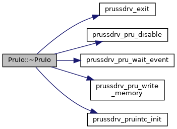
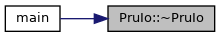
| PruIo::~PruIo | ( | ) |
Destructor to restore configurations and clear memory.
The destructor copies the original configuration to DRam (if any), loads new instructions to the PRU and start them. This PRU code restores the subsystems GPIOs, Control Module and ADC to their original configurations. Finaly the PRU gets powered off and the memory of the PruIo instance get freed.
The destructor cannot report error messages in member variable PruIo::Errr. Messages (if any) get sent directly to the ERROUT pipe of the operating system instead.
Wrapper function (C or Python): pruio_destroy().
Definition at line 284 of file pruio.bas.
| FUNCTION_CDECL_AS_ZSTRING_PTR PruIo::config | ( | BYVAL_AS_UInt32 | Samp = PRUIO_DEF_SAMPLS, |
| BYVAL_AS_UInt32 | Mask = PRUIO_DEF_STPMSK, |
||
| BYVAL_AS_UInt32 | Tmr = PRUIO_DEF_TIMERV, |
||
| BYVAL_AS_UInt16 | Mds = PRUIO_DEF_LSLMOD |
||
| ) |
Load configuration from host (ARM) to driver (PRU).
| Samp | Number of samples to fetch (defaults to 1). |
| Mask | Mask for active ADC steps (defaults to all 8 channels active in steps 1 to 8). |
| Tmr | Timer value in [ns] to specify the sampling rate (defaults to zero, MM and RB mode only). |
| Mds | Modus for output (defaults to 4 = 16 bit). |
This function is used to download the configuration from the host (ARM) to the driver (PRU). The PRU gets stopped (if running) and the new configurations get loaded. Also the Pru_Run instructions get re-initialized.
In case of an error the PRU will be disabled after this call. Otherwise it
Samp > 1), orSamp = 1).Samp = 0).The Samp parameter specifies the run mode (IO, RB or MM) and the number of samples to convert for each step. In IO mode (Samp = 1, default) sampling starts immediately and the index in the array AdcUdt::Value[] is equal to the step number. Inactive steps return 0 (zero) in this case.
| field | result of | defaults to |
|---|---|---|
| Value[0] | charge step | allways zero |
| Value[1] | step 1 | AIN-0 |
| Value[2] | step 2 | AIN-1 |
| ... | ... | ... |
| Value[8] | step 8 | AIN-7 |
| Value[9] | step 9 | undefined |
| ... | ... | ... |
| Value[16] | step 16 | undefined |
In MM (Samp > 1) the array AdcUdt::Value[] contains no zero values. Instead only values from active steps get collected. The charge step (step 0) returns no value. So when 3 steps are active in the Mask and Samp is set to 5, a total of 3 times 5 = 15 values get available in the array AdcUdt::Value[] (after the call to function PruIo::mm_start() ). The array contains the active steps, so when ie. steps 3, 6 and 7 are active in the Mask, the array contains:
| field | Mask = &b110010000 |
|---|---|
| Value[0] | 1. sample AIN-3 |
| Value[1] | 1. sample AIN-6 |
| Value[2] | 1. sample AIN-7 |
| Value[3] | 2. sample AIN-3 |
| Value[4] | 2. sample AIN-6 |
| Value[5] | 2. sample AIN-7 |
| Value[6] | 3. sample AIN-3 |
| Value[7] | 3. sample AIN-6 |
| Value[8] | ... |
Currently the number of samples is limited by the external memory allocated by the kernel PRUSS driver. This is 256 kByte by default (= 128 kSamples, see next table). Find informations on how to extend this memory block in section ERam.
| number of active Steps | max. Samples |
|---|---|
| 1 | 131072 |
| 2 | 65536 |
| 3 | 43690 |
| 4 | 32768 |
| 5 | 26214 |
| 6 | 21845 |
| 7 | 18724 |
| 8 | 16384 |
| ... | ... |
The Mask parameter specifies the active steps. Setting a bit in the Mask activates a step defined by the step configuration (by default bits 1 = AIN-0, 2 = AIN-1, ... up to 8 = AIN-7 are set, use function AdcUdt::setStep() to customize steps).
The highest bit 31 has a special meaning for customizing the idle step. By default the idle configuration is set like the configuration of the first active step, so that (in MM) the open delay can get reduced to a minimum for that step (if there's enough time left before restarting the ADC). By setting bit 31 the configuration from AdcUdt::Conf->St_p[0] is used instead.
The Tmr parameter specifies the sampling rate. It's the number of nano seconds between the starts of the ADC sampling process. The IEP timer gets used. It is configured to increase by steps of 5 (it counts in GHz, but runs at 200 MHz), so values like 22676 or 22679 results to the same frequency. Some examples
| Tmr [ns] | Sampling rate [Hz] |
|---|---|
| 1e9 | 1 |
| 1e6 | 1000 |
| 22675 | ~44100 |
Samp = 1).The Mds parameter specifies the bit encoding (range) of the samples. By default (Mds = 4) the samples from the ADC (12 bit) get left shifted by 4, so that they actually are 16 bit values and can get compared with samples from other ADC devices (like 16 bit audio data). Examples
| Mds | samples |
|---|---|
| 0 | 12 bit |
| 1 | 13 bit |
| 2 | 14 bit |
| 3 | 15 bit |
| >= 4 | 16 bit |
Wrapper function (C or Python): pruio_config().
Definition at line 452 of file pruio.bas.
| FUNCTION_CDECL_AS_ZSTRING_PTR PruIo::mm_start | ( | BYVAL_AS_UInt32 | Trg1 = 0, |
| BYVAL_AS_UInt32 | Trg2 = 0, |
||
| BYVAL_AS_UInt32 | Trg3 = 0, |
||
| BYVAL_AS_UInt32 | Trg4 = 0 |
||
| ) |
Start a measurement in MM.
| Trg1 | Specification for first trigger (default = no trigger). |
| Trg2 | Specification for second trigger (default = no trigger). |
| Trg3 | Specification for third trigger (default = no trigger). |
| Trg4 | Specification for fourth trigger (default = no trigger). |
This function starts a measurement in MM mode. The ADC configuration from the previous call to function PruIo::config() are used. The measurement either starts immediately or the start gets controlled by one (or up to four) trigger event(s).
Function are available to create trigger specifications:
MM mode runs endless. Stop it by up-loading a new configuration (by calling function PruIo::config() ).
Wrapper function (C or Python): pruio_mm_start().
| FUNCTION_CDECL_AS_ZSTRING_PTR PruIo::nameBall | ( | BYVAL_AS_UInt8 | Ball | ) |
Get header pin connected to CPU ball.
| Ball | The CPU ball number. |
This function creates a text description of the header pin connected to a CPU ball. The returned string is owned by this function and must not be freed.
When the CPU ball is not connected to a header pin, this function returns 0 (zero).
Definition at line 592 of file pruio.bas.
| FUNCTION_CDECL_AS_ZSTRING_PTR PruIo::Pin | ( | BYVAL_AS_UInt8 | Ball, |
| BYVAL_AS_UInt8 | Mo = 1 |
||
| ) |
Create a text description for a CPU ball configuration.
| Ball | The CPU ball number to describe. |
| Mo | The configuration to read (0 = Init, else Conf = default). |
This function is used to create a text description for the current state of a CPU ball (named pin when connected to one of the Beaglebone headers P8 or P9).
The description contains the pin name and its mode. Header pin names start with a capital 'P', CPU ball names start with a lower case 'b'. The detailed pinmux setting is only described for pins in mode 7 (GPIO mode). Otherwise only the mode number gets shown.
Definition at line 506 of file pruio.bas.
| FUNCTION_CDECL_AS_ZSTRING_PTR PruIo::rb_start | ( | ) |
Start ring buffer mode.
Start endless measuremnt in ring buffer mode. The active steps defined in the last call to function PruIo::config() get sampled at the specified sampling rate. The fetched values are stored in a ring buffer and the index of the currently stored value gets reported in DRam[0].
Inactive steps get no entry in the ring buffer, it only contains values from the active steps (as in MM mode). Use AdcUdt::Value[index] to read the samples.
RB mode runs endless. Stop it by up-loading a new configuration (by calling function PruIo::config() ).
Wrapper function (C or Python): pruio_rb_start().
| FUNCTION_CDECL_AS_ZSTRING_PTR() PruIo::setPin | ( | BYVAL_AS_Pruio__PTR | Top, |
| BYVAL_AS_UInt8 | Ball, | ||
| BYVAL_AS_UInt8 | Mo | ||
| ) |
Interface for pinmuxing function (internal).
| Top | The toplevel PruIo instance. |
| Ball | The CPU ball number (use macros from pruio_pins.bi). |
| Mo | The new modus to set. |
This is an internal function. It tries to set a new mode for a header pin (or CPU ball number) configuration. Each digital header pin is connected to a CPU ball. The CPU ball can get muxed to
The function changes pinmuxing, and will fail if (depending on system setup):
The function returns an error message in case of a failure, otherwise 0 (zero). The callback function gets connected in the constructor PruIo::PruIo(), depending on the system setup and current write privileges. The prefered method is the LKM method, which is used when the SysFs entry from the LKM is present, and libpruio has write access (needs administrator privileges = sudo ... or membership in user group 'pruio'). Otherwise the old-style device tree pinmuxing gets used, if present.
In case of LKM pinmuxing there're no restriction. Each CPU ball in the range zero to PRUIO_AZ_BALL can get set to any mode. Even claimed pins or CPU balls can get set to defined or undefined modes. The function executes faster than device tree pinmuxing (no OPEN ... CLOSE), boot-time is shorter (no overlay loading) and less memory is used.
| UInt8 PruIo::BallGpio[PRUIO_AZ_BALL+1] |
list of GPIO numbers, corresponding to ball index